 YIDINGAIR FILTRATION
Get a quote↗
YIDINGAIR FILTRATION
Technical Guides
2020-11-05 · Updated 2026-10-30
Choosing a HEPA terminal starts with the cleanliness class and airflow, then the unit type, layout, noise, ceiling and maintenance access. A step-by-step guide with the standards behind each step.
Key points
A HEPA terminal is the last point of the supply-air system: it holds the HEPA filter at the ceiling and discharges clean air into the room. It is tempting to start by picking a terminal model, but every later decision depends on what the room must achieve. The terminal type, the number of units, the filter class and the layout all follow from the required cleanliness and the process.
Cleanliness is defined by ISO 14644-1, which sets the maximum number of particles per cubic metre for each class [1]. For sterile medicinal products in Europe, EU GMP Annex 1 adds grades A to D with their own limits for the at-rest and in-operation states [2].
| ISO class | Max. particles ≥ 0.5 µm per m³ | Matching EU GMP grade (≥ 0.5 µm limits) | Typical uses |
|---|---|---|---|
| ISO 5 | 3,520 | Grade A (at rest and in operation); Grade B at rest | Aseptic filling, critical zones under unidirectional flow |
| ISO 6 | 35,200 | — | Semiconductor and electronics assembly areas |
| ISO 7 | 352,000 | Grade B in operation; Grade C at rest | Background rooms, compounding, medical device assembly |
| ISO 8 | 3,520,000 | Grade C in operation; Grade D at rest | Gowning rooms, packaging, support areas |
EU GMP Annex 1 also sets limits for particles ≥ 5 µm and for microbial contamination; check the full table for your grade.
There are three common forms of HEPA terminal, and the choice shapes everything else.
| Type | How it works | Best for |
|---|---|---|
| Disposable terminal module | Filter, housing and duct collar replaced as one unit | Simple installation, infrequent changes (e.g. AR602) |
| Room-side replaceable module | Housing stays; filter changed from inside the room | Frequent changes, limited ceiling access (e.g. AR601) |
| Fan filter unit (FFU) | Own fan draws air from the ceiling plenum | Large filtered ceilings, flexible layouts (e.g. AR603) |
The total supply airflow comes from the room design: the particles and heat the process releases, the recovery time required after a disturbance, and the pressure cascade between rooms. ISO 14644-4 covers design and construction, and ISO 14644-16 encourages setting airflow from these needs rather than from a fixed rule of thumb, because supply airflow is the largest energy cost in most cleanrooms [3][4].
For unidirectional zones the airflow follows from the velocity. EU GMP Annex 1 gives 0.36–0.54 m/s as a guidance value for unidirectional airflow at the working position in Grade A, unless a different value is justified [2]. Over a 1.2 × 0.6 m filter face, 0.45 m/s is about 1,170 m³/h.
For non-unidirectional rooms, divide the total airflow by the number of terminals. As an illustration only: a room of 6 × 5 × 3 m (90 m³) designed for 30 air changes per hour needs 2,700 m³/h, which three terminals of about 900 m³/h each can supply. Your design must set the actual air change rate.
Outlet velocity should be chosen from the supply method, the type of outlet, its mounting height, the air speed allowed in the occupied zone and the permitted noise level. As general design guidance for side-wall displacement outlets, the outlet is mounted below about 0.8 m with an outlet velocity of no more than about 0.2 m/s in civil buildings and 0.5 m/s in industrial buildings. Cleanroom terminals follow the design velocity for the cleanliness class, as in Step 2.
Every installed HEPA filter must be leak-tested in place, because most leaks occur at the seal and frame rather than in the media. ISO 14644-3 describes the scan test and the aerosol injection upstream of the filter [6]. A terminal design that cannot be tested is a problem that appears only at commissioning.
Room-side replaceable modules keep the housing and change only the filter from inside the room, which suits frequent changes. Disposable modules are simpler and fully renewed at each change.
The air speed through the inlet collar of the terminal. Keeping it within the permitted range limits noise and pressure drop.
When a large part of the ceiling must be filtered, when the layout may change, or when a ducted supply to every filter is impractical.
Usually not. H13 is the common choice for ISO 7–8 rooms. Use H14 where the specification or GMP grade requires it or where the room must reach ISO 5.
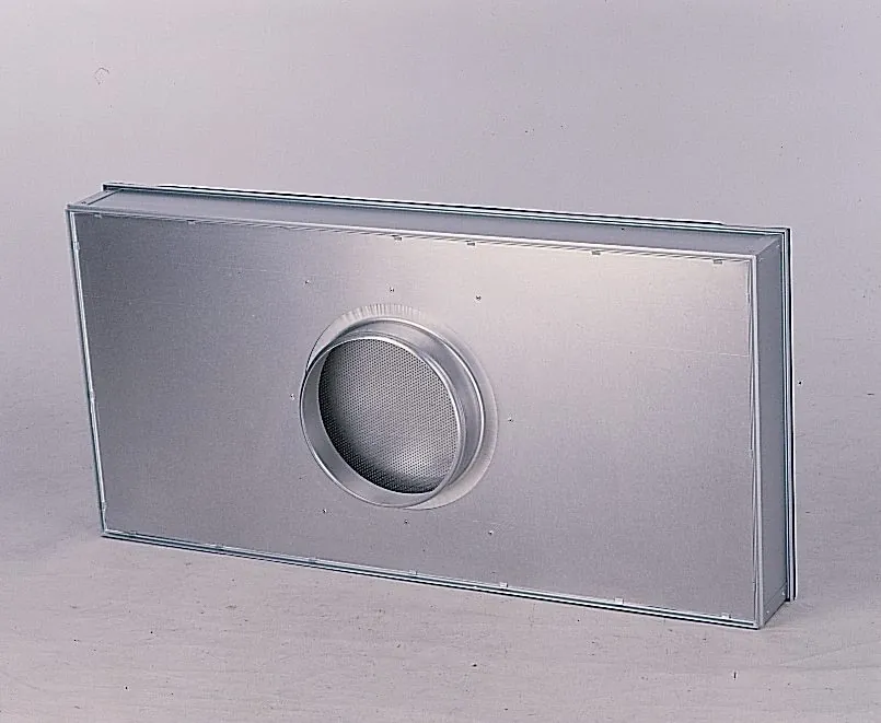
An integrated terminal filter and duct connection.
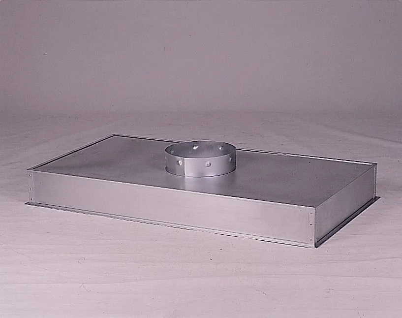
A ceiling filter housing with room-side access.
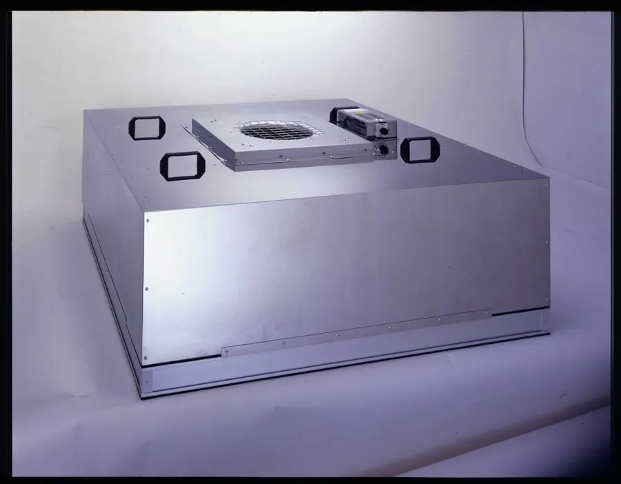
Integrated airflow and filtration for cleanrooms.
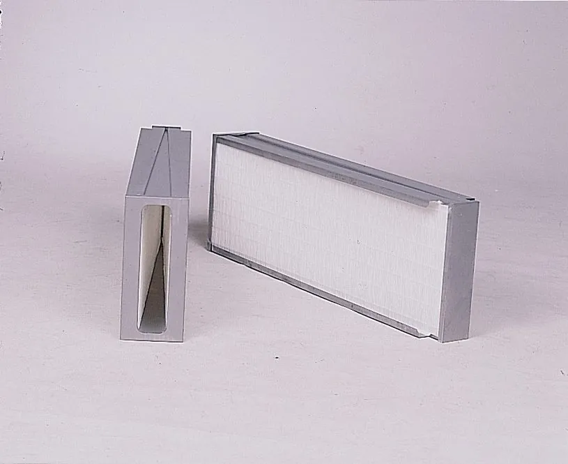
Terminal filter housings for cleanroom installations.